Current Location:HOME >> Solutions >>  New energy
Application of ZP-8621 Serial to Ethernet in Haixing County Wastewater Treatment Project

Time:2017-04-05 16:51:22
Haixing County sewage treatment plant design scale for the daily treatment of sewage 20,000 tons, the water standard for a level A. Water plant project using CASS + deep processing technology, the factory mainly by the grid and grit system, to enhance the pump room, CASS pool bioreactor system, aeration biofilter system, V-type filter system and sludge concentration system.
2 hardware design of sewage treatment control system
2.1 control system as a whole structure
Sewage treatment plant automation control system is divided into three levels of management, including production management level (central control room), site control level (PLC control station) and local control level. Site a variety of data collected through the PLC system, and through the trunk communication network - industrial Ethernet transmission to the central control room monitoring computer centralized monitoring and management. Similarly, the central control room monitoring computer control commands are also sent to the PLC through the channel monitoring and control terminal, the implementation of the decentralized control of the unit.
(1) Production management level (central control room)
Central management room management is the core of the system to complete the various parts of the sewage treatment process management and control, and to achieve the factory-level office automation. Through the high-resolution liquid crystal display and projector can be intuitive dynamic display of the whole process of the process section of the real-time conditions, the trend of the process parameters of the screen, the operator can grasp the whole plant operation.
(2) field control level (PLC station)
The control layer is the key to realize the automatic control of the system. According to the requirements of the automatic control process, the PLC of the control layer controls the equipment of the whole sewage treatment plant through the program to realize the acquisition of the field equipment and the parameters (such as pressure, flow, temperature, PH value, etc.) and the implementation of the management order.
(3) Local control level (equipment layer)
Turn the "local / remote" knob on the field control box to the "local" position and use the "start / stop" button on the box to enable the local start / stop control of the device.
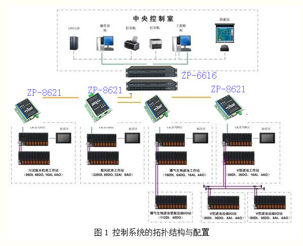
Haixing County sewage treatment plant control system topology and function configuration shown in Figure 1 using the product as follows:
Product Name: Industrial 232/485 to Ethernet Bidirectional Serial Server (Modbus)
Specifications Model: ZP-8621
Product Name: 16-port unmanaged industrial Ethernet switch (rack type)
Specifications Model: ZP-6616

2.2 Lower PLC system configuration
Hai Xing County sewage treatment plant automatic control system using PLC as the main controller to monitor and control the production process. The hardware part of the modular PLC control system mainly includes the CPU module, the I / O module, the communication module, the power module, the interface module and so on, according to the complexity of the control function and the control object's point number statistics corresponding configuration. According to statistics, the entire sewage plant needs PLC control I / O points a total of 829, is divided into four PLC control stations: 1 # PLC station only a master station; 2 # PLC station only a master station; 3 # PLC station Master station and a remote slave; 4 # PLC station includes master station and two remote slaves. The functions of each control station are as follows:
(1) sludge dewatering machine room workstation - 1 # PLC control station
Responsible for collecting water quality data of the water plant, as well as the grille system, swirl sagging system, sludge concentration system equipment, state acquisition and equipment control.
(2) Blower engine room workstation - 2 # PLC control station
Responsible for collecting CASS pool water quality data, as well as mixing system, decanter system, aeration system equipment status collection and equipment control.
(3) aeration biofilter workstation - # # PLC control station
Responsible for collecting aeration biofilter water quality data, as well as the secondary lifting system, aeration system, backwashing system equipment status collection and equipment control.
(4) V-type filter station - 4 # PLC control station
Responsible for the collection of V-type filter water quality data, as well as backwashing system, water system equipment, state and equipment control.
All in all, through the 485 to the Ethernet server to achieve the PLC control system master station and slave data exchange and data processing, the master station for each slave monitoring and human-computer interaction visibility.
2.3 Host monitoring system hardware configuration
The engineers and operator stations are located in the central control room, consisting mainly of two redundant operating stations, a set of projectors, a fault printer, a chart printer, and a set of UPS power supplies.
The two control stations in the central control room, one of which is the system monitoring and management computer, can be in the sewage treatment plant of various equipment status, process parameters in real-time detection and monitoring, provided to the operators, managers to run the management Man-machine interface, the other for the information monitoring and management computer, responsible for real-time and regular records and statements of production and printing.
 Software Design of Sewage Treatment Control System
3.1 Development of lower PLC control program
PLC design using Beijing and Lee when the company launched the Powerpro machine software, according to process requirements, the preparation of grille, to enhance the pumping station, swirl grit chamber, CASS pool, the second lift pump, aeration biofilter, V Filter and other subroutines. Sewage treatment process flow chart shown in Figure 2:
(1) grille system control
Grille system master for the grid unit, screw conveyor and ultrasonic level gauge. Its control can be set in the monitoring computer level control and timing control, when using liquid level control, is to rely on the grille before and after the liquid level to control the grid start and stop, when the liquid level difference to set the water level The PLC controller will issue a command to start the grid device; when the water level difference is less than the set lower limit, the grid unit will receive the stop signal from the PLC controller. The operator can set the device on the host computer start and stop level or run cycle.
(2) to enhance the pump control
Raise the pump control process requirements is based on the level of the level of automatic control to enhance the pump start and stop, the project site using dual-use equipment. When the pump fails, the fault pump will automatically cut out the automatic control program, the standby pump will automatically cut into the automatic control program. This long-term operation to ensure that the pump running time is roughly the same.
(3) swirl grit chamber system control
Swirl grit systems are controlled by agitators, Roots blowers and sand and water separators. The working principle of the system is as follows: The sewage enters from the tangential direction of the grit chamber, has a certain flow rate, so as to produce the centrifugal force of the gravel, so that the heavier gravel settles down to the bottom of the pool. The blades of the stirrer rotate to form axial vortices, producing a slight upward flow, which in turn discharges the sewage and flows into the next process for processing. Roots blower for the cyclone grit chamber to provide air, to mention the role of gas, and other gas will be directly transported to the sand and sand separator, to achieve a complete separation of gravel and sewage [2]. The control process requirements are as follows: stirrer, fan and sand separator to a certain period of operation, through the engineer station can set the running time.

(4) CASS pool system control
CASS pool system operation cycle is divided into four steps: aeration stage, the blower to the reaction tank oxygenation, this time the organic pollutants are microbial oxidation decomposition; precipitation stage, the use of microorganisms in the remaining DO DO further oxidative decomposition, activated sludge gradually Sedimentation to the bottom of the pool, the upper water becomes clear, the sludge return pump will be part of the activated sludge sent back to the pre-reaction zone, the excess sludge pump will be excess sludge sludge into the sludge dewatering; decanter stage, after the end of precipitation , The decanter placed at the end of the reaction tank began to work, from top to bottom gradually discharged supernatant; idle stage, decanter rise to the original position of the stage, waiting for the next cycle decanter. According to the above process requirements, the control program is written for each stage of the CASS process.
(5) aeration biological filter system control
Aeration fan its control process requirements: Aeration fan for 24 hours operation, 12:00 every day to replace a fan, so you can ensure that the three fans running roughly the same time.
Backwash system control is mainly to control the backwashing machine, backwash pump and valve to achieve the function of backwashing, every two days to conduct a backwash.
(6) V-type filter system control
V-type filter system automatically control the filter is the automatic backwash function. Subroutine control of the main equipment are backwash pump, backwash blowers, valves and instrumentation process parameters, once every two days backwash.
3.2 Host computer monitoring system to achieve
The control system on the host monitoring system using Beijing and Lee when the company's computer software FacView. The monitoring software will display the running status of the subsystems in the field, intuitively and realistically displayed on the industrial control machine in the central control room, so that the operator can obtain the field data and information in real time in the central control room and manage the operation of the sewage treatment plant. Friendly man-machine interface to the decentralized, single-loop monitoring and control system for a unified management, in addition to data alarm, historical data storage, report display, trend display and other functions.
The computer monitoring screen mainly includes the whole factory process chart, grille and grit system, CASS process, aeration biological filter, V-type filter, instrument data, trend, alarm, report, between the various screens can be free Switching Control Engineering Network All rights reserved

Previous Article:RS485 / 232 to WIFI wireless configuration Wang and Mitsubishi Omron Siemens PLC MODBUS wireless communication

Next Article:ZXTC company RS485 to Ethernet and serial to wifi in Zhengzhou subway use case

  • Links:
  • gpon and epon fiber optic equipment
  • RS232 to RS485 converter
  • NBiot module
  • Industrial Ethernet Switch
  • 5G router gateway
  • Minipcie serial card
  • Serial Server
  • Serial wifi module
  • ICP license: ZXTC Technology Co., LTD. ICP:粤ICP备14025924号-2

    .